ByJohn A
Pneumatic Couplings Help Maintain Consistent Airflow in Automated Manufacturing Equipment
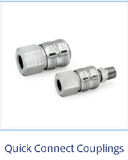
Automated production lines depend on a steady supply of compressed air, and much of that supply passes through small fittings which are seldom reviewed. Pneumatic couplings join hoses to tools, valves and machines, and their internal flow passage decides how much air actually reaches each actuator. When that passage matches the demand of the equipment, cycle times stay predictable.
Selecting pneumatic couplings by flow capacity, and not by thread size alone, gives automated equipment the consistent air delivery it needs to cycle at its designed speed. This post looks at where couplings sit in the air pathway, how a restrictive passage affects equipment response, what to compare before selection, and how routine leak checks keep compressed-air use under control.
Couplings as Part of the Compressed-Air Pathway
The Link Between Supply Line and Actuator: A coupling is the quick-connect point which joins a hose to a valve, cylinder, air tool or machine inlet, so every cubic foot of air on its way to the actuator passes through it. The compressor, dryer, regulator and main header prepare the air, but the coupling at the end of the line is often the last restriction before work gets done.
Why Small Passages Matter at the Point of Use: Air moving through a narrow bore loses energy to friction and turbulence, which shows up as pressure drop between the supply side and the tool side of the coupling. A cylinder sized for 90 psi at its port then receives less, so its available force drops and the stroke slows. The effect grows when several devices draw air at once.
A Restrictive Coupling Slows Equipment Response
Undersized Fittings on High-Demand Tools: An undersized coupling limits the volume of air a device can draw during each cycle, so the actuator reaches its end position later than designed. On a pick-and-place unit or a clamping fixture, a fraction of a second per stroke adds up across a shift. The controller and valves can be working correctly while the coupling limits the pace.
What Maintenance Teams Commonly Find: In everyday plant maintenance, technicians routinely trace slow or uneven cylinder strokes to a coupling which was swapped for a smaller size during a past repair. The replacement fit the thread and held pressure, so nobody questioned it. Restoring a coupling with the correct flow rating often brings the stroke speed back without any change to the valve or controller.
What Happens When a Review Is Postponed: When a restriction stays in place, plant teams tend to compensate by raising the system pressure at the compressor. This brings the slow station back up to speed but pushes every other device and every open leak to a higher pressure as well. Over time, the compressor runs longer and energy use climbs, while the original restriction becomes harder to spot.
Comparing Flow Capacity, Connection Size and Pressure Rating across the Circuit
Flow Capacity Before Thread Size: Manufacturers publish flow ratings for pneumatic couplings, usually in standard cubic feet per minute at a stated inlet pressure, and this figure is the most useful starting point for selection. Two couplings with the same 1/4 inch thread can differ widely in flow because body design and valve style change the internal passage. Comparing published flow data shows which option suits the tool.
Standard, High-Flow and Pressure-Rated Choices: A standard industrial coupling suits general air tools with moderate demand, while a high-flow design supports large cylinders and fast-cycling actuators at a higher price. The pressure rating should sit comfortably above the highest line pressure, including surges. The most dependable choice weighs the coupling against the hose bore and valve flow coefficient, since the smallest part sets circuit flow.
Leak Checks That Keep Compressed-Air Use in Line
Small Leaks with a Steady Cost: Compressed air is one of the more expensive utilities in a plant, because the electricity used by the compressor far exceeds the energy delivered at the tool. A worn seal or loose coupling releases air every hour the system is pressurized, including nights and weekends. This steady loss raises the total cost of ownership of every machine on the line.
Simple Leak Checks During Routine Rounds: Leak checks on couplings work best when they are part of a regular schedule. An ultrasonic leak detector picks up escaping air on a running floor, and a soap solution confirms the exact point on a quiet line. Replacing worn seals and reseating loose plugs takes minutes, and it returns air to the tools which need it.
Selection and Upkeep Points for Steady Airflow
Points Worth Checking: A short checklist helps maintenance and engineering teams keep pneumatic couplings matched to the equipment they serve. The points below cover selection, installation and upkeep, and each one supports steady cylinder speed while keeping compressed-air use close to what the process actually requires. Teams can apply them during new installs and routine audits alike.
- Compare each coupling’s published flow rating with the air demand of the device it feeds.
- Match coupling, hose and valve sizes so no single part narrows the flow.
- Choose a pressure rating comfortably above peak line pressure, including surges.
- Add coupling leak checks and seal replacement to routine maintenance rounds.
Consistent Air Delivery for Every Production Shift
Correctly sized pneumatic couplings keep actuators moving at their designed speed and help hold compressed-air use to what the process needs. Each month a restrictive or leaking coupling stays in service adds to energy bills and lost cycle time. Get in touch today to discuss the precision components and fittings your automated equipment needs for steady, efficient performance.